What Is Geometric Unsharpness?

When you’re testing products for quality and safety compliance, you need to ensure your imaging process produces the clearest, most reliable images possible. Minimizing geometric unsharpness is an essential step for creating better nondestructive testing (NDT) images.
This guide will explain everything NDT imaging technicians should know about geometric unsharpness and how it can impact their ability to identify issues accurately.
Understanding Geometric Unsharpness
Geometric unsharpness refers to the effect that your radiography setup can have on an image’s sharpness and clarity. Failure to consider the angles and other geometric factors in each part of your radiography setup can result in poorly defined images, which makes identifying nonconformances such as damage or foreign objects more difficult.
The X-ray penumbra is one example. A penumbra in X-ray images is a less-defined area at the edge of a test object usually resulting from geometric factors. Because it’s less clear than the rest of the image, it’s much harder to measure — as a result, operators will usually calculate it instead.
Why Is Geometric Unsharpness Important?
Minimizing geometric unsharpness is essential for producing the clearest possible images, which in turn enables you to identify and diagnose flaws, find foreign items or verify a dimension within the test object.
It’s also important for compliance with major industrial radiography codes and standards. Typically, geometric unsharpness must stay within 1/100 of the test object’s thickness to be acceptable. ASME V allows for a maximum of 0.07 inches for material thicknesses of more than 4 inches.
Factors Affecting Geometric Unsharpness
As with any experiment, adjusting the variables in an NDT scan will produce different outcomes. The three most important geometric factors in radiography include:
Source-to-Object Distance
The source-to-object distance (SOD) is a measure of the distance between the test object and the radiation source. It does not include the imaging detector.
It has an inverse relationship with geometric unsharpness, where increasing the SOD will reduce unsharpness. And, in reverse, bringing the object closer to the source will increase unsharpness.
Object-to-Detector Distance
Also known as the object-to-image distance (OID), the object-to-detector distance is a measure of the space between the center of the object’s mass and the imaging device’s detector.
The OID has a direct relationship with geometric unsharpness, so keeping that distance as small as possible will improve the image’s sharpness. Similarly, moving the object farther from the radiation source will result in greater geometric unsharpness.
It’s important to note that changing the OID also affects radiation intensity, which measures the concentration of power that is applied to each area of the test object. While a higher OID will create a more defined image, you will need to apply more intense radiation to the object or have a longer exposure to ensure a visible image.
Focal Spot Size
Also called source size, the focal spot size varies between different sources of X-rays or gamma rays. For example, an industrial X-ray tube used in a manufacturing plant will have a significantly larger source size than one used in health care settings.

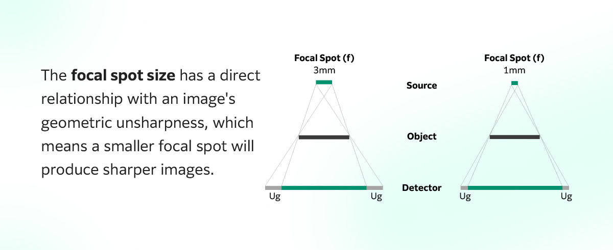
The focal spot size has a direct relationship with an image’s geometric unsharpness, which means a smaller focal spot will produce sharper images. Conversely, larger radiation sources will increase geometric unsharpness.
You can determine the source size for a scan by referencing the manufacturer’s specifications for the radiation source you’re using.
Film Characteristics
If using traditional X-ray imaging techniques, you should also consider how the type of film you use will impact the resulting image.
For example, the ISO, or the number indicating the film’s grain, has a direct impact on image clarity. Essentially, finer-grain films with a lower ISO will produce sharper images but require a longer exposure than coarser-grain films with higher ISOs.
Today, many testers use digital sensors instead of film, such as digital detector arrays or computed radiography equipment.
Measuring and Calculating Geometric Unsharpness
When measuring geometric unsharpness, you are primarily calculating the size of the penumbra to determine how much of the image is indistinct.
The basic geometric unsharpness formula is as follows: Ug = f · b/a.
The variables in this equation stand for:
- Ug: Geometric unsharpness
- a: Object-to-detector distance
- b: Object thickness
- f: Source size
To determine different outcomes or examine factors other than geometric unsharpness, you’ll need to adjust some of these variables.
Improving Image Quality
You can reduce geometric unsharpness by taking several basic steps:
- Increase SOD: Extending the distance between the radiation source and the test object will reduce geometric unsharpness, creating an image with greater definition.
- Use a finer focal spot: The finer the source size, the less geometric unsharpness you will see in the final image. Using a smaller X-ray tube can help you generate a clearer image.
- Reduce OID: Keeping the test object as close as possible to the imaging detector minimizes unsharpness in most applications.
- Use a different detector: Switch out the X-ray film you’re currently using for one with a lower ISO or adjust your equipment to see if it brings the penumbra more into focus. Additionally, calculating your contrast-to-noise ratio (CNR) regularly can help your technicians determine whether your current setup is producing the best results.
If none of the above work to make your imaging clearer, it might be best to consider upgrading your radiography equipment. Fujifilm offers a wide range of NDT imaging solutions for various industries, such as:
- Traditional X-ray film: If you prefer to use conventional X-ray technology in your imaging processes, we offer specialized X-ray film options for the aerospace and oil and gas industries. We also carry a full array of processing chemicals you’ll need to develop those images.
- Digital detector arrays: Digital detector arrays like our DynamIx FXR offers an efficient, safe and convenient industrial imaging solution for companies in various sectors.
- Imaging software: Our DynamIx VU software suite optimizes contrast for every image, making it a useful addition for a system that must minimize geometric unsharpness.
- Computed radiography systems: The DynamIx HR2 provides high imaging flexibility and improves image clarity by enabling users to customize processing parameters.
Why Trust Us?
When you’re looking for advice on improving your NDT processes, you need insight you can trust.
Fujifilm has decades of experience in radiographic imaging for various industrial applications, including NDT, quality assurance, regulatory compliance and more.
Essentially, our commitment to quality extends to the content we put out — so when you read our blog, you can be assured you’re finding the most accurate and up-to-date information available.
Improve Your NDT Imaging Quality With Solutions From Fujifilm
At Fujifilm, we strive to develop NDT solutions that help our customers get the results they need to comply with key industry regulations and lead their competition in creating high-quality products.
From high-resolution digital detector arrays to optimized diagnostic imaging software, our products can help you design a nondestructive testing system that meets your company’s specific needs. We also offer NDT training courses to ensure your team can help you get the most out of your technology.
Contact us today to learn more about our innovative NDT solutions and how they can benefit your business.


